GH- pneumatic film regulating valve
- Tel:0550-7516155
- Fax:0550-7513155
- Email:ghdq@ghdqkj.com
Description
First, general introduction
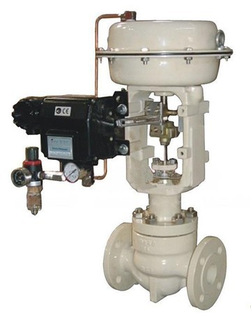
GH-ZVP, GH-ZXP series pneumatic thin film fine small single seat regulator adopts top oriented structure, with multi-spring film actuator. It has the advantages of compact structure, light weight, sensitive action, fluid channel is ~ streamlined, less pressure drop loss, large valve capacity, accurate flow characteristics, convenient disassembly and assembly. Widely used in the accurate control of gas, liquid, steam and other media, process parameters such as pressure, flow, temperature, liquid level to keep in the given value. Especially suitable for allowing leakage of small valve before and after the pressure difference is not large workplace. Nominal pressure grades of this series of products are PN10, 16, 25, 40, caliber range DN15 ~ 150. Applicable fluid temperature is -25℃ ~ +180℃. The leakage standard is class Ⅳ. The flow characteristics are a combination of linearity and equal percentage. Design units and users can choose according to specific working conditions.
Our products and domestic GH-ZMAP, GH-ZMBP, GH-ZJHP(fine small), GH-ZHAP, GH-ZHBP, GH-VP, GH-HTS, GH-ZHTS, GH-HLS, GH-HTS and other single-seat regulator equivalent. Single seat regulator in the automatic control valve code P.
Ii. Specification of model preparation
The model name is ZaPb-cd-e-f
a— Valve body type: V or X, representing two - way or three - way valve respectively
b— Original valve body series number, such as 31, 41, 45, 52, etc
c— Pressure grade (MPa) : 10, 16, 25, 40
d— Mode of action :K is gas open, B is gas closed
e— Nominal diameter 15, 25, 40, 50, etc
f— Flow coefficient (water medium)
For example: GH-ZVP31-10K-DN65-5 specifically refers to the nominal pressure level of PN10, the valve body adopts SIEMENS VVF31 series, caliber is 65mm, flow coefficient is 5 air open pneumatic film two-way regulator.
3. Connection size and standard
• Flange according to GB/T9113-2000(default standard)
• Flange end distance according to GB12221-89(other standards shall be specified)
• Actuator gas signal interface: internal thread M10x1(DN≤ 100), internal thread M16x1.5(DN>100)
Four, installation and maintenance
(I). Installation
1. Preparation before installation
a. Due to the regulating valve long-distance transportation, handling, long-term storage and other factors, for general occasions, must *** check the appearance; Observe whether there is damage and loose screws. The screws at the sealing place must be tightly fastened to ensure reliable sealing, and the pressing screws on the packing should be fastened in the appropriate position to ensure the sealing of the packing box without reducing the accuracy of the whole machine. For important use occasions or when the medium is corrosive, harmful medium, it should also carry out strength, sealing, leakage test and precision test.
b. Pipes shall be cleaned prior to installation and filters and discharge valves shall be installed on the inlet side of valves to remove sand, rust and other impurities.
2. Problems should be considered before installation:
a. Safety: The safety of personnel and equipment during installation, testing, operation and maintenance shall be taken into account.
b. Control performance: It should be ensured that there is enough straight pipe section at the inlet of the regulating valve, and the pressure loss of the piping system should be consistent with the pressure calculated when the regulating valve is selected, so as to ensure the actual flow capacity and flow characteristics required remain unchanged.
c. Ease of manual operation: The installation position of the valve shall be convenient for the operator to operate the valve by looking at the value displayed on the indicator. If the bypass valve is used for manual operation, then the flow characteristics and stroke of the bypass valve should be consistent with the selection of the regulator.
d. Accessibility: The possibility of local disassembly and maintenance of the regulating valve should be taken into account.
e. Regulating valve group: the regulating valve should be set by bypass in general, so that when the automatic control system fails, or the maintenance of the regulating valve with the cut off valve isolation, with the bypass valve adjustment, in order to adapt to the continuous production of equipment.
3. Installation
a. Regulating valve best vertical installation on the pipeline, when forced to tilt installation, as far as possible to avoid horizontal installation. Tilt mounting and valves should be supported from heavy and vibration occasions.
b. Avoid heavy stress when the valve body is installed in the pipe. (Different axes and other reasons)
c. The medium flow direction should be consistent with the arrow on the valve body.
d. Install the regulating valve on the highest level pipe section of the process piping. There should be a drainer on the inlet or outlet side piping of the valve to prevent the phenomenon of water hammer and obtain a faster regulating effect.
e. The air source should be dry and oil-free.
f. Regulating valve should be installed in the environment temperature does not exceed -25 ~ +550C place.
(2) Maintenance
Control valve maintenance is generally divided into preventive maintenance and fault maintenance, preventive maintenance is a kind of planned maintenance. The maintenance of regulating valve usually has the following contents:
1, valve cleaning: the regulator is a part of the process pipeline, will be process fluid pollution, for a control valve for steam, air, sui gas, water and other non-toxic medium, just wash with water or steam purge can be. But for toxic, corrosion, explosion and radioactive pollution of the valve cleaning, first of all to understand the nature of pollutants, and then choose the corresponding cleaning methods, so as not to cause harm to repair personnel.
2, valve disassembly: in order to check all parts of the regulating valve in order to determine the scope of repair and replacement, the actuator and valve must be completely disassembled. If the parts of the regulator rust, these parts before repair to remove rust. But all machined surfaces should be protected before rust removal. Spool, stem, valve seat, push rod and other precision parts must be placed in good order to prevent damage. Special tools should be used to remove seat.
3. Maintenance of main parts.
a. Seats: Brushed, corroded and worn seats usually need to be replaced. Small rust spots and worn surfaces can be repaired by machining.
b. Spool and stem: The damaged surface should be replaced with spare parts provided by the factory. The repaired or replaced spool and valve seat should be ground.
c. Damage to the guide and sealing surface of the push rod: for the reaction actuator, it is necessary to replace new parts, and for the positive actuator, it can be used after proper repair.
d. Compression spring: If there are cracks and other defects affecting the strength, it must be replaced.
e. Wearing parts: The main wearing parts of the regulator are: packing, sealing gasket, O - ring, diaphragm. The packing, sealing gasket and O-ring removed during each overhaul are all replaced with new parts. The diaphragm shall be inspected for any signs of cracks, aging or abrasion that may indicate future failure, and replacement shall be determined based on the results of the inspection. Diaphragm generally *** more than 2 ~ 3 years to ** replace.
4. Assembly and debugging
The assembly of the regulating valve is not complicated. Attention should be paid to accurate alignment, the bolt is evenly tightened on the diagonal, and the appropriate lubricant is selected for the friction point of the actuator and valve stem.
After assembly, the regulating valve should be tested according to the product standard in the factory test items and methods, and during this period can more accurately adjust the packing force, spool closing position and valve positioner.
X. Please provide the following information when ordering:
• Name, model and purpose of regulating valve
• Nominal diameter (mm), nominal pressure (MPa), operating temperature and range
• Pressure before valve, pressure after valve
• Medium name and status, medium flow
• Operation mode of the whole machine (air on or air off), instrument wind (air source) pressure
• Requirements of the attachment:
Electric-gas valve positioner, air filter pressure reducer, solenoid valve, position retaining valve, valve position transmitter, (top mounted) handwheel, connecting end flange, etc.
• Valve body flange standard (if not specified, our company supplies according to GB9113-2000)
• Structure length of valve body (flange face distance L) (If not specified, our company shall supply according to GB12221-89)
• Other special requirements (such as corrosion resistance requirements, explosion-proof requirements, leakage level limit requirements, etc.)
